|
您当前的位置: 气体分离设备商务网 → 行业书库 → 在线书籍 → 《气体爆炸手册(GAS EXPLOSION HANDBOOK )》
Formation of Explosive Gas Clouds When combustible gas or evaporating liquids are accidentally released into the atmosphere, a combustible fuel-air cloud may be formed. Figure 3.1 shows possible events in case of an accidental release.
If the gas cloud formed by the release is outside the flammable concentration range (i.e. below LFL or above UFL, see section 4.1), or the ignition source is lacking, no combustion will occur. Subsequently the gas cloud will dilute and disappear. In case of an immediate ignition, a fire will develop. The most dangerous situation, however, will occur if a large flammable premixed fuel-air cloud is formed and ignites. A serious explosion may then result. The objective of this chapter is to: i) Describe the difference between a jet release and an evaporating pool. ii) Describe experimental results from jet releases in a 1:5 scale model of an offshore module. iii) Describe FLACS code facilities for simulation of gas dispersion. iv) Discuss the formation of a combustible gas cloud and ignition.
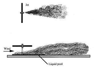
3.1 Jet Releases and Evaporating Pools The released substance can be a gas, an evaporating liquid or a gas-liquid (two phase) flow. The source will be characterised as a jet release (i.e. gas, two phase or evaporating liquid), or a diffuse release, i.e. evaporating pool. A jet release and a diffuse source are shown in Figure 3.2.
The two sources have quite different characteristics. The jet release will have a high momentum and establish a strong flow field due to additional air entrainment. Recirculation zones may be generated where the gas concentration can reach a combustible level. For jet releases in a building or offshore module, the recirculation can result in build-up of large combustible clouds. The evaporating pool will act as a diffuse release source and the wind forces and buoyancy will control the dispersion process. The flow velocities will be much lower than for the jet release. If the evaporating liquid forms a dense gas, a layer of combustible gas may be formed at the ground level, or in a lower compartment. Similarly in an open area a dense gas cloud will have the tendency to intrude into confined spaces such as buildings. The intrusion of combustible gas into such confined or semi-confined spaces poses serious problems. As discussed in Chapters 5,6 and 9 to 11, confinement will generally cause high explosion pressures. 3.2 Gas Dispersion Tests in a 1:5 Scale Offshore Module Bjørkhaug and Bjerketvedt (1990) have performed gas dispersion tests in a 1:5 scale offshore module. Gaseous methane and propane were released inside a module through various nozzles (420 mm diameter). The reservoir was a 3m3 tank and the initial pressure was 5-20 barg. The module had forced ventilation with a bulk flow velocity of 0 m/s to 1.0 m/s.
One of the objectives with this test was to establish the degree of homogeneity of the cloud in the module. Figure 3.3 shows the concentration versus time at two different locations at the same level. The upward-pointing release starts at 20 sec. In the early phase there is a difference in concentration, but after about 10 sec. the curves are quite similar. Figure 3.4 shows the concentration in two similar tests at the same place but at different heights.
In these tests there are relatively small variations in concentration. Further the effect of forced ventilation was investigated. Figure 3.5 shows the concentration in three tests with the same source but with different wind velocities (i.e. bulk flow) through the module.
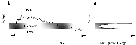
Initially the concentration rise was similar for all three cases, at a certain concentration level however, the transportation of fuel out of the module was equal to the leak rate and the concentration profile is flattening out. The higher the wind speed, the lower the concentration where the concentration profile is flattening out. As the reservoir is emptied, the concentration gradually decreases. If the fuel concentration was on the rich side, it would have to pass through the flammable region. The main findings from these experiments are:
3.3 Gas Dispersion Simulations Using FLACS Storvik (1991) has used FLACS89 to simulate high momentum jet leaks and subsequent gas dispersion in a scaled-down model of an offshore module. Gas dispersion simulations with high momentum jet leaks usually require many hours of CPU usage due to short time-step and long leak duration (several minutes). In FLACS89 the high momentum jet is modelled analytically conserving the mass and momentum flow, and is coupled to the resolution of the flow field in the simulation domain. This procedure reduces the need for high spatial resolution near the jet and is an effective approach to simulate high momentum leaks. Forced ventilation is simulated using a wind as boundary condition. This is useful for simulation of gas dispersion with specified wind speed and turbulence parameters. In summary: FLACS89 has built-in facilities for handling realistic gas dispersion scenarios including external wind fields, various types of leak sources (jet or diffuse) and wall-functions to account for boundary layer effects.
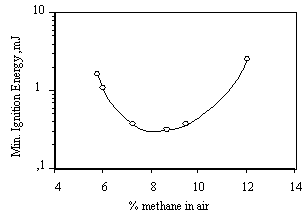
Figure 3.6 shows an example of a contour plot from a jet release in an offshore module. Shaded areas show fuel concentration within the flammability limits. The high momentum jet and a fairly homogeneous gas cloud on the upper deck can be identified. The plot also depicts how the gas on the upper deck is diluted by the flow from the lower deck through the grating in the intermediate deck. Results from FLACS dispersion simulations can be used as input parameters to characterise gas clouds in FLACS gas explosion simulations. A modified version of FLACS has been used to simulate release of gas from high pressure pipelines (Sand et al., 1996), taking non-ideal gas effects into account. The results showed that the lower flammability limit of gas-air mixture reaches its most remote downstream position relatively early, before retracting somewhat due to increased entrainment of air. 3.4 Gas Cloud and Ignition To ignite a gas cloud requires an ignition source with sufficient strength. The minimum ignition energy depends on fuel concentration and type of fuel.
As the reservoir is emptied, the release rate will gradually be reduced and the gas concentration in the cloud will decrease. A weak ignition source will "sit and wait" until the gas cloud has the right composition before it ignites. In several accidental gas explosions the time from the release was initiated until the explosion occurred was 10 to 20 min. In such cases it is probable that the gas concentration is decreasing at the time of ignition. It should be stated, however, that this is speculative.
When the ignition source is strong the gas cloud will be ignited when the edge of the cloud reaches the ignition source. If the ignition source is weak, however, the source may fail to ignite the cloud in the early phase of the dispersion process or ignite only a small part of the cloud. Subsequently, a homogeneous large gas cloud may be formed. This cloud enters into the flammable concentration as the reservoir is emptied and a weak ignition source may ignite the cloud. This discussion shows some of the complexities involved in assessing ignition probability and formation of explosive gas clouds. 3.5 Ventilation in Compartments Kletz (1987) claims that "the best building has no walls". This is true with respect to gas explosion safety. In an open building the natural ventilation will enhance the gas dispersion and if an explosion occurs, the open areas will relieve the pressure. If the release rates are small there is no doubt that mechanical ventilation systems can counteract the formation of explosive gas clouds. However, for a massive release, the forced ventilation rate will in general be too low. A ventilation system may also transport gas from one area to another. 3.6 Guidelines
注意:本栏目所有书籍均来至于网络,如果其中涉及了您的版权,请及时联系我们,我们在核实后将在第一时间予以删除!
|


